BC_MOTION

Boundary conditions

*BC_MOTION
"Optional title"
coid
entype, enid, bc${}_{tr}$, bc${}_{rot}$, csysid${}_{tr}$, csysid${}_{rot}$, $t_{beg}$, $t_{end}$
pmeth${}_1$, direc${}_1$, cid${}_1$, $sf_1$, fid${}_1$
.
pmeth${}_n$, direc${}_n$, cid${}_n$, $sf_n$, fid${}_n$

Parameter definition

Variable
Description
coid
Command ID (optional)
entype
Entity type
options: N, NS, P, PS, ALL, G, GS
enid
Entity identification number
bc${}_{tr}$
Translational constraints
options: 0, X, Y, Z, XY, YZ, ZX, XYZ
bc${}_{rot}$
Rotational constraint
options: 0, X, Y, Z, XY, YZ, ZX, XYZ
csysid${}_{tr}$
Coordinate system ID for translational constraints
csysid${}_{rot}$
Coordinate system ID for rotational constraints (0 for rotation around COG)
$t_{beg}$
Activation time
$t_{end}$
Termination time
pmeth${}_1$
Method used to prescribe motion (acceleration/velocity or displacement)
options: A, V, D
direc${}_1$
Direction of prescribed motion
options: X, Y, Z, RX, RY, RZ
cid${}_1$
ID of a CURVE or FUNCTION defining prescribed motion
$sf_1$
Scale factor for curve ordinate values
default: 1
fid${}_1$
ID of optional activation function
default: not used
.
pmeth${}_n$
Method used to prescribe motion (acceleration/velocity or displacement)
options: A, V, D
direc${}_n$
Direction of prescribed motion
options: X, Y, Z, RX, RY, RZ
cid${}_n$
ID of a CURVE or FUNCTION defining prescribed motion
$sf_n$
Scale factor for curve ordinate values
default: 1
fid${}_n$
ID of optional activation function
default: not used

Description

Definition of kinematic boundary conditions. When referring to a local cylindrical coordinate system (csysid${}_{tr}$), X corresponds to the radial direction, Y to the tangential direction and Z to the axial direction.

The optional activation function is used to define more complex switches than a simple activation/deactivation time. fid${}_n$ refers to the ID of a FUNCTION. The prescribed motion (or rotation) is active if the specified FUNCTION returns a value > 0.

Reaction forces, torques and external work are written to the ASCII file prescribed.out. Resulting torques on rigid bodies are expressed in the local rotational coordinate system (csysid${}_{rot}$). If a rotational coordinate system has not been defined, then the torques are presented with respect to the center-of-gravity.

Example

Constraining rigid body with part

The following commands constrain the rigid body with part ID 333 in translation (all directions) and in rotation around the global x- and y-axes. A prescribed spin (100 rad/s) is defined around the z-axis. The title will show up in the ASCII file prescribed.out and helps the user distiguish between different BC_MOTION definitions in the input deck.

*BC_MOTION "this is a title" P, 333, XYZ, XY V, RZ, 123 *CURVE 123 0.0, 100.0 1.0, 100.0
Constraints applied in cylindrical coordinate system

Constraints can be applied in a cylindrical coordinate system. The example below constrains the tangential motion of a node set. The polar coordinate system has its center at (%xc, %yc, %zc) and its axial direction is (%xn, %yn, %zn). The tangential motion of the nodes in the set is constrained by setting bc${}_{tr}$=Z.

*PARAMETER %xc = 1.0 %yc = 2.0 %zc = 3.0 %xn = cos(30) %yn = sin(30) %zn = 0.0 *BC_MOTION "constrain tangential motion" NS, 1, Z, 0, 123 *COORDINATE_SYSTEM_FIXED 123, [%xc], [%yc], [%zc] [%xn], [%yn], [%zn]
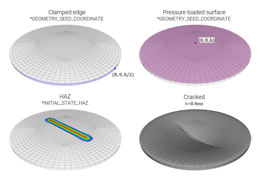
Clamping of disk edge using seed coordinate

Two surfaces on a disk, edge and top face, are defined using GEOMETRY_SEED_COORDINATE. The edge is referenced by BC_MOTION and the top face is used by LOAD_PRESSURE.

*UNIT_SYSTEM SI *PARAMETER %R = 0.05, "Disk radius" %h = 0.002, "Disk thickness" %p0 = 2.0e7, "Peak pressure" %t0 = 0.0005, "Pressure decay time" %tend = 0.001, "Termination time" # # --- TIME --- # *TIME [%tend] # # --- MESH --- # *COMPONENT_CYLINDER "Disk" 1, 1, 1, 20 0, 0, 0, 0, 0, [%h], [%R] *CHANGE_P-ORDER P, 1, 3 # # --- MATERIAL --- # *MAT_METAL 1, 7800.0, 210.0e9, 0.3, 1 1 *PROP_DAMAGE_CL 1, 2 1.0e9 *FUNCTION 1 sigy0 + 1.0e9*epsp^0.3 # # --- HAZ --- # *INITIAL_STATE_HAZ PATH, 100, P, 1, 101, 102 *CURVE "sigy0" 101 0, 5.0e8 0.005, 1.0e9 1.0, 1.0e9 *CURVE "D0" 102 0.0, 0.8 0.005, 0.0 1.0, 0.0 *PATH 100 [-%R/2], 0, [%h/2] [%R/2], 0, [%h/2] # # --- PART --- # *PART "Disk" 1, 1, 0, 0, 0, 0, 2.0 # # --- BC --- # *BC_MOTION "Clamp disk" 1 G, 1, XYZ *GEOMETRY_SEED_COORDINATE "Edge" 1 [%R], 0, [%h/2] # # --- LOAD --- # *LOAD_PRESSURE "Disk pressure" 1 G, 2, 2 *GEOMETRY_SEED_COORDINATE "Top face" 2 0, 0, [%h] *FUNCTION "Pressure" 2 %p0 * exp(-t/%t0) *END
Pressure loaded disk