
MAT_POWDER_BURN
FE
Material properties
Beta command
This command is in the beta stage and the format may change over time.
"Optional title"
mid, $\rho$, $E$, $\nu$, did
$C_v$, $\gamma$, $e_0$, $b$, fid, $T_i$, $p_i$, $t_i$
local, $A$, $B$, $n$
$\eta_d$, $a_d$, $m_d$, $n_d$, $p_d$
Parameter definition
Description
This material command is used to model unburned propellant as rigid or elasto-plastic grains and its combustion products as gas lumped into an overlapping CFD grid. The grains are assumed rigid, unless $E \gt 0$.
Solid propellant
If $E \gt 0$ then the flow stress is defined as:
$\displaystyle{ \sigma_y = A + B(\varepsilon_{eff}^p)^n }$
Gas products
The pressure of the generated gases is defined as:
$\displaystyle{ p = \frac{\gamma-1}{1 - \rho b} e}$
where $\rho$ is the current gas density and $e$ is the current specific internal energy. Note that $b$ has the units $m^3/kg$.
Burn rate
By default (local=0) the burn rate is uniform for each grain. That is, the average pressure and temperature is calculated and used for all element faces on the grain. If local=1, then the local pressure and temperature define the local burn rate for each individual element face.
Ignition
A grain ignites if the local gas pressure $p_{CFD} \geq p_i$ and the grain surface temperature $T_g \geq T_i$. If $t_i$ is defined, then the grain surface temperature evolves according to:
$\displaystyle{ \dot T_g = \frac{T_{CFD} - T_g}{t_i} }$
It is also possible to define the grain heating with a user defined function (fcn):
$\displaystyle{ \dot T_g = f(T_g, p_{CFD}, v_t) \cdot \left(T_{CFD} - T_g \right) }$
Here $p_{CFD}$ is the local gas pressure and $v_t$ is the gas flow velocity relatively the grain surface. The command POWDER_BURN_IGNITE can also be used to ignite grains inside a specific region.
Propellant energy
$e_0$ is either defined as a constant or as a CURVE with energy per unit mass versus burn distance. The instant energy release per unit mass of emitted gases is $(1-\eta) \cdot e_0$. The remaining energy, $\eta \cdot e_0$, represents uncombusted gases or small energetic particles.
Delayed energy release (burning fragments)
A delayed energy release, $\eta \cdot e_0$, can be used to model small emitted reactive particles that essentially follow the gas flow. A dimensinless variable $0 \leq \lambda \leq 1$ marks the progress of released energy.
$\displaystyle{ \dot\lambda = a_d \cdot (1 - \lambda)^{m_d} \cdot \left( \frac{p}{p_d} \right)^{n_d} }$
The local energy release rate per unit mass of emitted gas is:
$\displaystyle{ \dot q = \dot\lambda \cdot \eta \cdot e_0 }$
Example
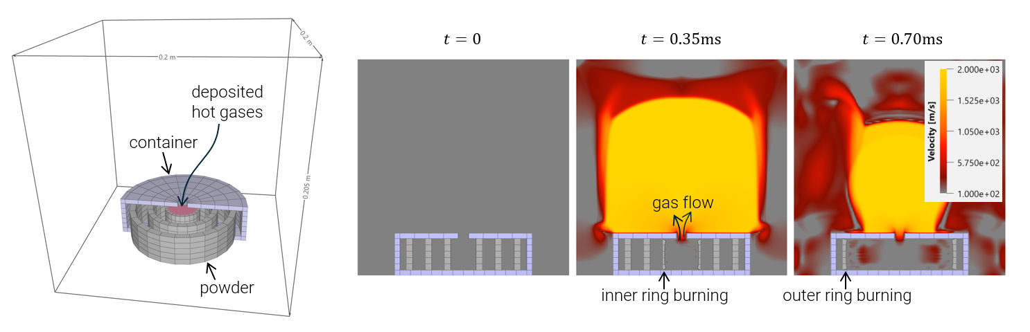
Propellant burning inside a small cylinderical space
Idealized rings of propellant burning inside a cylindrical container. The inner ring is ignited by depositing hot gases at time zero, using CFD_GAS.
User defined grain heating function
Simple example of a grain heating function:
$\displaystyle{\dot{T}_g = C_h \cdot \left(1 + \frac{v_t}{v_h} \right) \cdot \frac{p_{CFD}}{p_h} \cdot \left( T_{CFD} - T_g \right)}$
where $v_t$ is the gas flow velocity relatively the grain surface, $p_{CFD}$ is the local gas pressure and $(C_h, v_h, p_h)$ are user defined constants.